


Integrating a surge protection device into a photovoltaic system is not simply a matter of plugging in a component and moving on. It requires a deliberate, engineering-informed approach that accounts for the unique electrical characteristics of both the AC and DC sides of the installation. Lightning-induced transients, switching surges, and grid disturbances can all introduce destructive voltage spikes that travel through the system, damaging inverters, combiner boxes, monitoring equipment, and even the PV modules themselves. Without proper surge protection device placement on both sides, a single transient event can result in costly downtime and equipment replacement.
This article walks through the complete integration logic for surge protection device deployment across both the DC string and array side and the AC grid-connection side of a PV system. Whether you are designing a rooftop commercial installation or a utility-scale ground-mount project, understanding where to place each surge protection device, how to select the right specifications, and how to wire and maintain these components correctly is essential for long-term system reliability. The guidance here is grounded in practical field engineering and aligned with IEC 61643 and IEC 62305 standards that govern surge protection in photovoltaic environments.
Understanding Surge Risks in PV Systems
Why PV Systems Are Particularly Vulnerable
Photovoltaic systems are exposed to the outdoor environment continuously, which makes them inherently susceptible to lightning and atmospheric discharge events. The long cable runs between PV arrays and inverters act as antennas, capturing induced electromagnetic energy from nearby lightning strikes even when a direct strike does not occur. This induced energy travels as a transient overvoltage along both the DC cabling from the modules and the AC cabling toward the grid connection point.
On the DC side, the open-circuit voltage of a PV string can already be several hundred volts under standard conditions. When a transient is superimposed on this baseline voltage, the combined spike can easily exceed the withstand capability of inverter input stages, bypass diodes, and junction box components. On the AC side, grid switching events, capacitor bank operations, and utility faults introduce fast-rising transients that can damage the inverter output stage and any connected metering or communication equipment.
A properly selected and installed surge protection device on each side intercepts these transients before they reach sensitive electronics. The device clamps the voltage to a safe level and diverts the surge current to ground, protecting the downstream equipment. Without this protection layer, even a moderate transient can degrade insulation, trigger nuisance tripping, or cause immediate component failure.
The Two-Sided Nature of PV Surge Exposure
One of the most common mistakes in PV surge protection planning is treating the system as having only one vulnerable point. In reality, surges can enter from either direction. A lightning event near the array injects energy into the DC side, while a grid disturbance or nearby industrial load switching injects energy from the AC side. Both pathways must be protected independently with a dedicated surge protection device at each location.
The inverter sits between these two sides and is the most expensive single component in most PV installations. It is also the most vulnerable, because its power electronics operate close to their voltage limits during normal operation. A surge protection device on the DC input terminals of the inverter and another on the AC output terminals creates a protective envelope around this critical component. This dual-side approach is not optional for systems in high-lightning-risk zones or for any installation where downtime costs are significant.
DC Side Surge Protection Device Integration
Placement at the String Combiner Box
The first and most important location for a surge protection device on the DC side is at the string combiner box, also called the DC combiner or array junction box. This is where multiple PV strings are brought together before the combined DC output travels to the inverter. Placing a surge protection device here intercepts transients at the earliest possible point in the DC circuit, preventing them from propagating further into the system.
For this position, the surge protection device must be rated for the maximum DC open-circuit voltage of the array under worst-case temperature conditions. For systems operating at 1000 V DC, the device must carry a voltage protection rating and maximum continuous operating voltage that comfortably exceed this value. Common ratings used in utility-scale and commercial PV installations include 1000 V DC and 1500 V DC variants, with impulse current ratings of 20 kA or 40 kA depending on the lightning protection zone classification of the site.
The surge protection device at the combiner box should be connected between each DC pole and the protective earth conductor. In a two-pole configuration, this means one device between the positive rail and earth and one between the negative rail and earth. Some installations use a three-pole or combined device that handles both poles simultaneously. The choice depends on the system grounding configuration and the specific surge protection device product design.
Placement at the Inverter DC Input
Even when a surge protection device is installed at the combiner box, a second device at the inverter DC input terminals is strongly recommended for systems with long cable runs between the combiner and the inverter. Cable inductance limits how effectively a remote surge protection device can clamp a fast-rising transient at the inverter terminals. The residual voltage that appears at the inverter input after the combiner-box device has operated can still be high enough to stress the inverter's input capacitors and IGBT modules.
The surge protection device at the inverter DC input acts as a second line of defense, catching any residual transient energy that was not fully absorbed by the upstream device. This cascaded approach, sometimes called a Type 1 plus Type 2 coordination scheme, is standard practice in well-engineered PV installations. The device at the inverter input is typically a Type 2 surge protection device with a lower discharge current rating, since the upstream device has already absorbed the bulk of the surge energy.
Wiring the DC-side surge protection device correctly is critical. The connection leads between the device and the DC bus should be as short as possible, ideally under 50 cm, to minimize the inductive voltage drop that adds to the clamping voltage seen by the inverter. Using the shortest possible lead length and avoiding unnecessary bends in the connection wiring are practical steps that significantly improve the effectiveness of the surge protection device installation.
AC Side Surge Protection Device Integration
Placement at the Inverter AC Output
On the AC side, the primary location for a surge protection device is at the inverter AC output, typically inside or immediately adjacent to the AC disconnect or combiner panel. This position protects the inverter's output stage from transients arriving from the grid and also protects any monitoring, metering, or communication equipment connected to the AC bus at this point.
The surge protection device selected for the AC side must be rated for the system's AC voltage, which is typically 230 V single-phase or 400 V three-phase for most commercial and industrial PV installations. The device must also be compatible with the grid frequency and must have a maximum continuous operating voltage that accounts for normal grid voltage fluctuations. For three-phase systems, a three-pole or four-pole surge protection device covering all line conductors and the neutral is required.
The impulse current rating for the AC-side surge protection device should be selected based on the lightning protection zone and the distance from the main service entrance. A Type 2 surge protection device with a 20 kA or 40 kA rating is appropriate for most PV AC output applications. Where the installation is in a high-risk lightning zone or where the AC cable run to the main switchboard is long, a Type 1 device with a higher impulse current rating may be warranted at the main switchboard level.
Placement at the Main AC Switchboard or Point of Common Coupling
For larger PV systems that feed into a main switchboard or a point of common coupling with other loads, an additional surge protection device at the switchboard level provides system-wide protection. This device handles surges that enter from the utility grid side and prevents them from reaching not only the inverter but also other sensitive loads connected to the same switchboard.
The coordination between the surge protection device at the inverter AC output and the one at the main switchboard follows the same cascaded logic as the DC side. The switchboard-level device, typically a Type 1 or combined Type 1 and Type 2 device, handles the initial high-energy surge, while the inverter-level device catches residual energy. This layered approach ensures that no single device is overwhelmed and that the protection remains effective across a wide range of surge magnitudes and waveforms.
When selecting the surge protection device for the main switchboard, it is important to verify that the device's voltage protection level is coordinated with the impulse withstand voltage of the inverter and other connected equipment. The protection level of the surge protection device must be lower than the equipment's withstand voltage to ensure that the device clamps the transient before it can cause damage. This coordination check is a mandatory step in any professional PV surge protection design.
Grounding, Wiring, and Installation Best Practices
The Role of a Low-Impedance Ground System
A surge protection device can only perform its function effectively if it has a low-impedance path to ground through which it can divert surge current. The grounding system of the PV installation is therefore just as important as the surge protection device itself. A high-resistance or poorly bonded ground connection will cause the surge protection device to develop a high voltage across its terminals during operation, reducing its effectiveness and potentially allowing damaging voltages to reach protected equipment.
For PV installations, the grounding system should include a dedicated earth electrode at the array location, bonded to the structural mounting system and to the DC-side surge protection device ground terminal. The AC-side surge protection device should be bonded to the main protective earth conductor of the building or facility. All ground connections should use appropriately sized conductors, typically 6 mm² or larger for surge protection device ground leads, to handle the impulse current without excessive voltage drop.
Equipotential bonding between the DC ground, the AC ground, and the structural ground of the PV mounting system is essential for preventing ground potential rise during a surge event. When different parts of the system are at different ground potentials during a transient, the voltage difference between them can damage equipment even if each individual surge protection device is functioning correctly. A unified, low-impedance ground system eliminates this risk.
Monitoring and Maintenance of Installed Devices
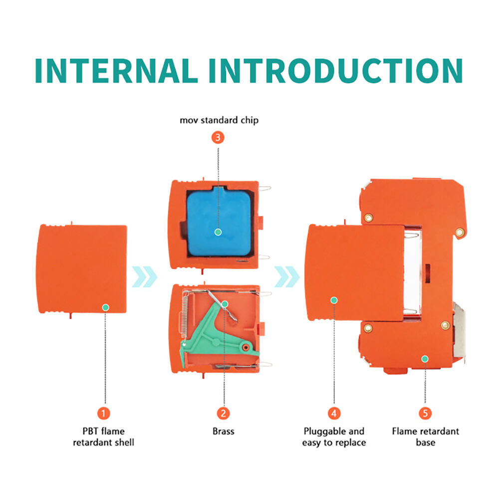
A surge protection device is a consumable protective component. Each time it absorbs a surge event, it expends some of its protective capacity. After a major lightning event or a series of smaller surges, the device may reach the end of its service life and require replacement. Most modern surge protection device products include a visual status indicator, typically a window that changes color or a flag that drops, to signal when the device has been degraded and needs replacement.
Incorporating surge protection device status checks into the regular maintenance schedule of the PV system is a straightforward but often overlooked practice. A quarterly visual inspection of all installed devices, combined with a post-storm check after any significant lightning activity in the area, ensures that the protection remains active. Some advanced surge protection device models include remote monitoring contacts that can be wired into the system's SCADA or monitoring platform, enabling automatic alerts when a device needs replacement.
Replacement of a degraded surge protection device should be carried out promptly. Operating a PV system with a failed surge protection device on either the AC or DC side leaves the inverter and associated equipment fully exposed to the next transient event. Given the relatively low cost of a surge protection device compared to the cost of inverter replacement or system downtime, timely maintenance is a straightforward economic decision.
Selecting the Right Surge Protection Device for PV Applications
Key Electrical Parameters to Evaluate
Selecting the correct surge protection device for a PV application requires evaluating several key electrical parameters. The maximum continuous operating voltage of the device must exceed the highest voltage that will appear across its terminals under normal operating conditions, including any grid voltage tolerance. For DC-side devices, this means accounting for the maximum open-circuit voltage of the PV array at the lowest expected ambient temperature, since PV module voltage increases as temperature decreases.
The nominal discharge current and maximum impulse current ratings determine how much surge energy the surge protection device can handle. These ratings should be matched to the lightning protection zone classification of the installation site, which is determined by the local lightning ground flash density and the physical characteristics of the structure. A surge protection device with a 40 kA impulse current rating provides a higher safety margin than a 20 kA device and is appropriate for exposed locations or high-value installations.
The voltage protection level of the surge protection device, expressed in kilovolts, indicates the maximum voltage that will appear across the device terminals during a standardized surge test. This value must be lower than the impulse withstand voltage of the equipment being protected. For PV inverters, the DC input impulse withstand voltage is typically specified in the product datasheet, and the surge protection device must be selected so that its protection level provides an adequate margin below this value.
Compliance Standards and Certification Requirements
For PV applications, the surge protection device should comply with IEC 61643-11 for AC-side devices and IEC 61643-31 for DC-side devices. These standards define the test methods, performance requirements, and marking requirements for surge protective devices used in low-voltage power systems and PV installations respectively. Compliance with these standards ensures that the device has been independently tested and verified to perform as specified under standardized surge conditions.
In addition to IEC compliance, many markets and project specifications require CE marking and TUV certification for surge protection device products used in PV systems. These certifications provide additional assurance of product quality and manufacturing consistency. When specifying a surge protection device for a commercial or utility-scale PV project, verifying that the product carries the appropriate certifications for the target market is an important step in the procurement process.
Some grid operators and insurance providers have specific requirements for surge protection device installation in grid-connected PV systems. Reviewing these requirements early in the design process ensures that the selected surge protection device meets all applicable standards and that the installation method complies with local electrical codes. Non-compliant installations may face issues during grid connection approval or insurance claims following a surge-related loss event.
FAQ
Do I need a surge protection device on both the AC and DC sides of my PV system?
Yes. Surges can enter a PV system from either direction — from the array side during lightning events or from the grid side during switching transients. Installing a surge protection device only on one side leaves the inverter and associated equipment exposed to transients from the unprotected side. A complete protection strategy requires a surge protection device at the DC combiner or inverter DC input and another at the inverter AC output or main switchboard.
What voltage rating should I choose for a DC-side surge protection device?
The surge protection device must have a maximum continuous operating voltage that exceeds the maximum open-circuit voltage of the PV array under the coldest expected temperature conditions. For systems designed to operate at 1000 V DC, a surge protection device rated for 1000 V DC or higher is required. For 1500 V DC systems, a device rated at 1500 V DC must be used. Always add a safety margin above the calculated maximum array voltage when selecting the device rating.
How often should I inspect or replace a surge protection device in a PV installation?
A visual inspection of all installed surge protection device units should be performed at least quarterly and after any significant lightning activity in the area. Most devices include a status indicator that changes appearance when the device has been degraded. Any surge protection device showing a fault indication should be replaced promptly. Even without visible degradation, devices in high-lightning-activity areas may benefit from replacement every five to seven years as a preventive measure.
Can I use a standard AC surge protection device on the DC side of a PV system?
No. Standard AC surge protection device products are not suitable for DC applications. DC circuits do not have a natural current zero-crossing, which means that once a surge protection device begins conducting, it must actively interrupt the follow current to avoid a sustained arc. DC-rated surge protection device products are specifically designed with arc-quenching mechanisms and component ratings appropriate for DC voltage and current characteristics. Using an AC device on a DC circuit creates a serious fire and safety risk.
Table of Contents
- Understanding Surge Risks in PV Systems
- DC Side Surge Protection Device Integration
- AC Side Surge Protection Device Integration
- Grounding, Wiring, and Installation Best Practices
- Selecting the Right Surge Protection Device for PV Applications
-
FAQ
- Do I need a surge protection device on both the AC and DC sides of my PV system?
- What voltage rating should I choose for a DC-side surge protection device?
- How often should I inspect or replace a surge protection device in a PV installation?
- Can I use a standard AC surge protection device on the DC side of a PV system?