
 EN
EN



Solar photovoltaic systems depend on reliable electrical infrastructure to deliver consistent power generation and protect valuable equipment from environmental threats. Within these systems, the combiner box serves as a critical junction point where multiple string circuits converge before connecting to the inverter. As solar installations grow in scale and complexity, the risk of voltage surges caused by lightning strikes, grid disturbances, or switching operations increases proportionally. Integrating surge protection directly within a combiner box design transforms this junction point into a comprehensive safety node that prevents catastrophic equipment damage and ensures operational continuity. Understanding the technical requirements, component selection criteria, and installation methodologies for embedding surge protective devices within combiner box assemblies enables engineers and system designers to create resilient solar infrastructure that withstands harsh environmental conditions while maintaining optimal performance.
The integration process requires careful consideration of electrical specifications, physical layout constraints, thermal management requirements, and compliance standards that govern solar installations. A properly designed combiner box with integrated surge protection must coordinate voltage ratings with system architecture, match current-handling capacities to string configurations, and provide accessible mounting positions for maintenance activities. This comprehensive approach to surge protection integration goes beyond simply adding components to an enclosure; it involves systematic planning of conductor routing, grounding architecture, and protection coordination that ensures surge currents find safe dissipation paths without compromising the primary power delivery function of the combiner box. Engineers must balance protection effectiveness with practical installation requirements, cost considerations, and long-term reliability to create solutions that deliver measurable value throughout the solar system's operational lifespan.
Understanding Surge Protection Requirements for Combiner Box Applications
Voltage Surge Characteristics in Solar Photovoltaic Systems
Solar installations face multiple surge threat vectors that originate from both external environmental sources and internal system operations. Lightning-induced surges represent the most severe threat category, with direct strikes potentially introducing transient voltages exceeding tens of thousands of volts within microseconds. Even indirect lightning activity occurring several kilometers from the installation site can couple electromagnetic energy into solar array wiring through inductive and capacitive mechanisms, generating damaging overvoltages at the combiner box input terminals. The long cable runs typical in utility-scale solar farms act as efficient antennas for electromagnetic disturbances, making surge protection integration within the combiner box essential rather than optional.
Beyond lightning phenomena, solar systems generate internal surges during normal switching operations and fault conditions. Inverter startup sequences, string isolation switching, and rapid cloud transient responses create voltage spikes that propagate backward through the DC collection system toward the combiner box. Ground fault conditions and arc fault events produce high-frequency transients that stress insulation systems and degrade electronic components over time. A well-designed combiner box with integrated surge protection addresses these diverse threat mechanisms through coordinated protection stages that clamp overvoltages before they reach sensitive inverter input stages while allowing normal operating voltages to pass unimpeded.
Electrical Specifications for Surge Protective Devices
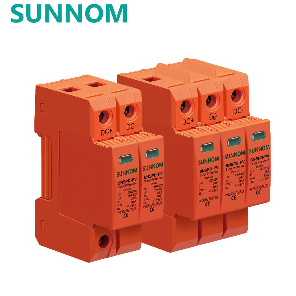
Selecting appropriate surge protective devices for combiner box integration begins with establishing the maximum continuous operating voltage that matches the solar array configuration. For systems operating at 1000V DC, the surge protection components must withstand this voltage continuously without degradation while maintaining readiness to clamp transient overvoltages. The voltage protection level, which defines the maximum voltage that appears across the protected equipment during a surge event, must remain below the withstand capability of downstream inverters and monitoring equipment. Type 2 surge protective devices typically used in combiner box applications offer voltage protection levels ranging from 2.5 to 4 kilovolts depending on the base voltage rating and varistor technology employed.
Current-handling capacity represents another critical specification that determines surge protection effectiveness within a combiner box design. The nominal discharge current rating, typically specified as an 8/20 microsecond waveform, indicates the surge current magnitude the device can safely divert to ground repeatedly throughout its service life. For solar applications, surge protective devices integrated within the combiner box should provide minimum nominal discharge current ratings of 20 kiloamperes per pole, with enhanced protection schemes utilizing 40 kiloampere-rated components for installations in high lightning-density regions. The maximum discharge current or impulse current rating defines the single-pulse survival threshold, with quality devices offering capabilities of 65 kiloamperes or higher to withstand worst-case direct lightning exposure scenarios.
Protection Coordination Within System Architecture
Effective surge protection integration within a combiner box requires coordination with other protective elements distributed throughout the solar installation. A layered protection strategy positions coarser protection stages at the service entrance and array periphery, with progressively finer protection stages closer to sensitive equipment. The combiner box occupies a middle position in this protection cascade, receiving pre-limited surge energy from array-level devices while providing final voltage clamping before the inverter input terminals. This coordinated approach prevents any single protection stage from absorbing excessive energy while ensuring that each device operates within its designed response characteristics.
The let-through energy of surge protective devices integrated within the combiner box must complement the withstand ratings of connected equipment. Modern inverters specify maximum surge immunity levels in their technical documentation, typically ranging from 4 to 6 kilovolts for differential mode surges and 6 to 8 kilovolts for common mode disturbances. The combiner box surge protection design must guarantee that actual let-through voltages remain below these thresholds across the full spectrum of expected surge magnitudes. Proper coordination also considers the timing characteristics of protective devices, ensuring that faster-responding components at the combiner box level activate before slower upstream protection, creating a definitive energy dissipation hierarchy that guides surge currents away from sensitive components.
Physical Integration Methods for Surge Protection Components
Enclosure Selection and Environmental Protection
The physical enclosure that houses the combiner box assembly establishes fundamental parameters for surge protection component integration. NEMA-rated enclosures appropriate for outdoor solar installations must provide ingress protection against dust, moisture, and physical impact while accommodating the dimensional requirements of surge protective devices, fusing components, and terminal blocks. NEMA 4X enclosures constructed from corrosion-resistant materials such as stainless steel or fiber-reinforced polymer composites offer superior longevity in coastal or industrial environments where atmospheric contaminants accelerate degradation of standard painted steel enclosures.
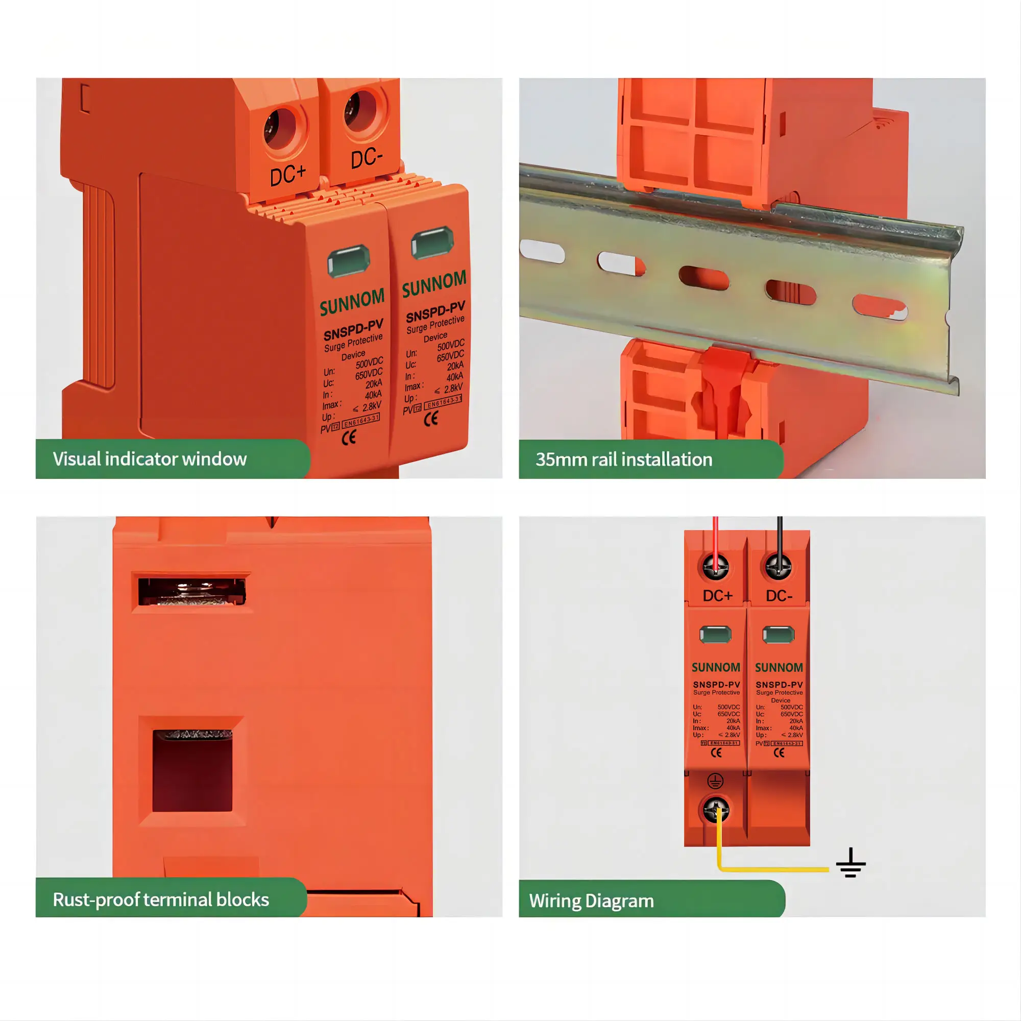
Internal layout planning within the combiner box enclosure must allocate dedicated mounting positions for surge protective devices that facilitate proper conductor routing and thermal management. Surge protection modules generate heat during normal operation and experience significant temperature increases during surge events, requiring adequate spacing from adjacent components and enclosure walls. Mounting surge protective devices on DIN rail assemblies provides standardized positioning and enables tool-free replacement when devices reach end-of-life indicators. The physical arrangement should position surge protection components between the string input terminals and the main output busbar, creating a logical electrical path that mirrors the intended current flow during both normal operation and surge conditions.
Grounding Architecture for Effective Surge Current Dissipation
Successful surge protection integration within a combiner box depends critically on establishing low-impedance grounding paths that enable rapid surge current dissipation without creating secondary voltage stresses. The grounding conductor connecting surge protective devices to the system grounding electrode should follow the most direct physical path possible, avoiding unnecessary bends or loops that introduce inductive impedance. For combiner box applications, grounding conductors should maintain minimum cross-sectional areas of 6 square millimeters for copper conductors, with larger sizes appropriate for installations anticipating high lightning exposure or serving large array capacities.
The connection methodology between surge protective device terminals and the grounding busbar significantly influences protection effectiveness. Ring terminals secured with lockwashers and appropriate torque specifications provide reliable mechanical and electrical contact that resists vibration-induced loosening over years of outdoor service. The grounding busbar within the combiner box should connect to the external grounding system through multiple parallel conductors when possible, reducing the effective impedance of the ground reference path. Star-point grounding configurations that connect all surge protective devices to a common low-impedance point before routing to the external grounding electrode help prevent ground loop currents that could otherwise couple surge energy between protected circuits.
Conductor Routing and Separation Requirements
The physical routing of conductors within the combiner box enclosure influences both surge protection effectiveness and electromagnetic compatibility. Input conductors from individual strings should maintain separation from output conductors feeding the inverter to minimize capacitive coupling of high-frequency surge energy. Creating distinct routing channels for positive, negative, and grounding conductors using plastic cable management systems or barriers helps maintain organized installations that simplify troubleshooting and future modifications while supporting proper conductor identification throughout the assembly.
The conductor length between string input terminals and surge protective device connection points should remain as short as practical to minimize the voltage drop that occurs across conductor impedance during surge events. This voltage drop adds directly to the let-through voltage of the surge protective device, potentially compromising protection effectiveness if excessive conductor lengths introduce significant inductive impedance. Similarly, the conductor length between surge protective devices and the grounding busbar should not exceed 500 millimeters in typical installations, with shorter lengths preferred for systems expecting severe surge exposure. Using oversized conductors for critical surge current paths reduces resistive voltage drop and improves thermal performance during high-energy surge events.
Electrical Connection Strategies for Surge Protection Integration
Series Versus Parallel Connection Topologies
Surge protective devices integrate within combiner box designs using either series or parallel connection topologies depending on device technology and protection philosophy. Parallel-connected surge protective devices, the most common configuration for solar applications, connect between the DC power conductor and ground, presenting very high impedance during normal operation and transitioning to low impedance during surge events. This topology allows normal operating current to flow unimpeded through the combiner box while diverting surge currents to ground through the protective device, combining effective protection with minimal impact on system efficiency.
Series connection topologies position surge protective components directly in the current path, requiring the device to carry full load current continuously. While less common for primary surge protection in combiner box applications, series devices offer advantages in specific scenarios such as protecting monitoring circuits or providing backup disconnection capabilities. Hybrid protection schemes combine parallel-connected primary surge protective devices with series-connected secondary protection elements to create multi-stage protection cascades within a single combiner box enclosure. These sophisticated designs provide enhanced protection for critical installations while maintaining accessibility for maintenance and inspection activities.
Fusing Coordination with Surge Protection
Integrating surge protection within a combiner box design requires careful coordination with string-level fusing to ensure that protective devices operate in the intended sequence during both fault and surge conditions. String fuses provide overcurrent protection for individual photovoltaic source circuits, while surge protective devices address transient overvoltage threats. The fuse ratings must allow surge protective devices to conduct their rated discharge current without nuisance fuse operation, typically achieved by selecting fuse time-current characteristics that remain above the surge protective device's energy let-through envelope for transient durations.
The physical positioning of fuses relative to surge protective devices within the combiner box influences protection effectiveness and fault isolation capabilities. Locating fuses upstream of surge protection connection points ensures that a failed surge protective device can be isolated without interrupting other string circuits, maintaining partial system operation during maintenance activities. However, this arrangement requires that surge protective devices possess adequate short-circuit withstand ratings to survive downstream fault currents until upstream fuses clear. Alternative designs position surge protective devices ahead of individual string fuses, providing common surge protection for all strings while accepting that a surge device failure may require complete combiner box isolation for repair activities.
Terminal Block Selection for Surge Current Paths
Terminal blocks within the combiner box serve as the mechanical and electrical interface between field wiring and internal protection components, making their selection critical for surge protection integration success. High-current terminal blocks rated for the continuous operating current of the solar strings must also withstand the brief but intense current pulses associated with surge events without sustaining contact damage or developing high-resistance connections. Terminal blocks with nickel-plated copper current bars and pressure-plate connection mechanisms provide superior performance compared to screw-clamp designs that may loosen over time due to thermal cycling and vibration.
The current-carrying capacity of terminal blocks should include adequate derating for elevated ambient temperatures common in outdoor combiner box installations exposed to direct solar radiation. Terminal blocks rated for 125 degrees Celsius operating temperature maintain reliable performance when enclosure internal temperatures exceed 70 degrees Celsius during peak summer conditions. Dedicated grounding terminal blocks with enhanced contact pressure specifications ensure low-resistance connections for surge protective device grounding conductors, supporting effective surge current dissipation. Color-coded or physically separated terminal blocks for positive, negative, and grounding conductors reduce installation errors and simplify visual inspection of connection integrity.
Monitoring and Maintenance Features for Integrated Surge Protection
Status Indication Systems for Surge Protective Devices
Effective surge protection integration within a combiner box design incorporates status indication features that enable rapid assessment of protection system health without requiring electrical testing or device removal. Visual indicators using mechanically actuated flags or windows provide at-a-glance confirmation that surge protective devices remain functional, with color changes from green to red signaling end-of-life conditions requiring device replacement. These passive indication systems operate without external power requirements, maintaining reliability even during grid outages or system maintenance periods when electrical monitoring systems may be offline.
Advanced combiner box designs integrate electrical status contacts from surge protective devices into remote monitoring systems that provide continuous protection status visibility. Normally closed contacts that open when a surge protective device fails enable automated alarm generation and remote notification of maintenance requirements, reducing the mean time to repair and minimizing the period during which the installation operates with compromised surge protection. Integrating these status signals with the broader supervisory control and data acquisition system creates comprehensive asset health monitoring that supports proactive maintenance scheduling and accurate service life documentation for warranty and insurance purposes.
Access and Replaceability Considerations
The physical layout within a combiner box must facilitate surge protective device inspection and replacement without disrupting other system functions or requiring extensive disassembly of adjacent components. Mounting surge protective devices on readily accessible DIN rail sections near the enclosure door allows technicians to perform visual status checks and device replacements efficiently. Adequate working clearance around surge protection components, typically 75 millimeters minimum on all sides, provides space for tool access and safe handling of devices that may retain residual charge following surge events.
Modular surge protective device designs that separate the active surge suppression element from the mounting base enable rapid replacement of failed components while maintaining secure electrical connections. These plug-in configurations reduce service time and minimize the risk of wiring errors during replacement activities compared to hard-wired surge protective devices requiring conductor disconnection and reconnection. Documentation labels within the combiner box enclosure should specify the correct replacement part numbers, voltage ratings, and current ratings for installed surge protective devices, ensuring that maintenance personnel install compatible components that maintain the original protection coordination scheme.
Testing and Verification Procedures
Commissioning a combiner box with integrated surge protection requires systematic verification that all protective components function correctly and meet specified performance parameters. Insulation resistance testing between DC power conductors and ground verifies the integrity of surge protective device varistors, with measurements exceeding 1 megohm at nominal system voltage indicating proper device condition. Ground continuity testing confirms low-resistance paths between surge protective device ground terminals and the external grounding electrode, with resistance values below 1 ohm validating effective surge current dissipation capability.
Periodic maintenance inspections should include visual examination of surge protective device status indicators, verification of terminal connection tightness using calibrated torque tools, and thermal imaging to identify abnormal temperature patterns that might indicate degraded connections or component failures. Comparing thermal images taken during peak generation periods over multiple years enables trend analysis that predicts maintenance requirements before actual failures occur. Documentation of surge protective device installation dates, status indicator readings, and any surge events recorded by monitoring systems creates a service history that supports warranty claims and informs replacement scheduling decisions based on actual operating experience rather than arbitrary time-based intervals.
Compliance and Certification Requirements for Surge Protection Integration
Electrical Code Requirements for Solar Combiner Boxes
Solar combiner box designs incorporating surge protection must comply with applicable electrical codes that govern photovoltaic system installations in the jurisdiction of deployment. The National Electrical Code in the United States addresses surge protection requirements in Article 690, which mandates surge protective devices for photovoltaic systems on dwellings and permits their use as optional equipment for other installation types. Local amendments and authority having jurisdiction interpretations may impose more stringent requirements, making early engagement with permitting officials essential during the design phase for combiner box assemblies with integrated protection.
Code compliance extends beyond mere presence of surge protective devices to encompass installation methods, conductor sizing, and grounding practices that support effective protection performance. Grounding conductors for surge protective devices must meet minimum size requirements specified in code, typically not smaller than 14 AWG copper for individual device connections and sized according to feeder conductor ampacity for common grounding busbars. The routing of grounding conductors must avoid sharp bends exceeding 90 degrees and maintain support at intervals not exceeding 600 millimeters to prevent physical damage and maintain low impedance. Documenting compliance with these installation requirements through photographs and inspection checklists facilitates approval processes and creates valuable as-built records for future maintenance activities.
Product Certification Standards for Surge Protective Devices
Surge protective devices integrated within combiner box assemblies should carry certification marks demonstrating compliance with recognized product safety standards. In North American markets, Underwriters Laboratories Standard UL 1449 Fourth Edition establishes safety and performance requirements for surge protective devices, including requirements specific to photovoltaic applications. This standard addresses electrical endurance, short-circuit withstand capability, abnormal overvoltage withstand, and end-of-life failure mode requirements that ensure devices fail safely without creating fire or shock hazards. Specifying UL 1449 Listed surge protective devices for combiner box integration provides assurance that components meet minimum safety thresholds recognized by code officials and insurance underwriters.
European and international markets reference IEC 61643-11 and IEC 61643-31 standards for low-voltage surge protective devices and surge protective devices for photovoltaic installations specifically. These standards establish classification systems based on installation location and test requirements that validate surge current handling, voltage protection levels, and follow current interruption capabilities. Combiner box designs destined for international deployment should incorporate surge protective devices certified to both UL and IEC standards when possible, or clearly specify regional variants that substitute appropriately certified components while maintaining equivalent protection performance. Third-party certification marks such as TÜV or CE marking provide additional market access advantages and demonstrate commitment to internationally recognized quality standards.
System-Level Testing and Documentation
Complete combiner box assemblies with integrated surge protection may require system-level testing beyond individual component certifications to validate overall protection coordination and electrical safety. Type testing programs evaluate complete assemblies under simulated surge conditions, verifying that the coordinated response of fuses, surge protective devices, and connection hardware provides the intended protection performance. These tests apply standardized surge current waveforms at various magnitudes while measuring let-through voltages and verifying that no component failures occur below rated discharge current levels. Successful type testing provides documented evidence of protection system effectiveness that supports marketing claims and provides technical assurance to system designers and end users.
Manufacturing documentation for combiner box assemblies with integrated surge protection should include detailed electrical schematics showing surge protective device connection points, grounding architecture, and conductor routing paths. Bill of materials documentation must specify exact part numbers, voltage ratings, and current ratings for all surge protective devices to ensure that production units maintain consistency with type-tested configurations. Quality control procedures should verify proper surge protective device installation, ground connection integrity, and status indicator functionality for each manufactured unit, with inspection records retained to support traceability requirements and warranty administration. This comprehensive documentation approach ensures that the surge protection integration methods validated during design and testing transfer reliably to production units deployed in the field.
FAQ
What voltage rating should surge protective devices have in a 1000V DC combiner box?
Surge protective devices integrated within a 1000V DC combiner box should possess a maximum continuous operating voltage rating of at least 1200V DC to provide adequate safety margin above the nominal system voltage. This voltage rating ensures the surge protective device remains in high-impedance mode during normal operation, including transient overvoltages caused by temperature variations and open-circuit conditions. The voltage protection level, which indicates the clamped voltage during surge events, should remain below 3500V to protect typical inverter input stages rated for 4000V surge immunity. Systems operating in regions with high lightning activity may benefit from surge protective devices rated for 1500V maximum continuous operating voltage to provide enhanced safety margins and extended service life under frequent surge exposure conditions.
How often should surge protective devices in a combiner box be inspected?
Surge protective devices integrated within combiner box assemblies should undergo visual inspection at least annually, with more frequent inspections recommended for installations in high-lightning regions or following known severe weather events. These inspections should verify status indicator displays show normal operating condition, confirm absence of physical damage or discoloration on device housings, and check that terminal connections remain tight with no signs of overheating or corrosion. Automated monitoring systems that report surge protective device status remotely enable continuous condition awareness, reducing the reliance on periodic manual inspections while still requiring annual on-site verification. Devices showing end-of-life indicators should be replaced promptly to maintain protection effectiveness, as degraded varistors may fail to clamp subsequent surge events adequately or develop excessive leakage current that wastes energy and generates heat.
Can surge protection be added to an existing combiner box installation?
Retrofitting surge protection into existing combiner box installations is technically feasible when adequate physical space exists within the enclosure and proper grounding infrastructure is available. The retrofit process requires careful evaluation of available mounting positions, conductor routing paths, and clearance to existing components to ensure the added surge protective devices do not create safety hazards or compromise the original overcurrent protection scheme. Electrically, the existing grounding busbar must provide sufficient capacity for the additional surge current paths, and the connection between the combiner box ground and the system grounding electrode must meet low-impedance requirements for effective surge dissipation. Installations lacking adequate grounding infrastructure may require supplemental grounding electrode installation before surge protective devices can deliver meaningful protection benefits. Consulting with qualified electrical engineers ensures that retrofitted surge protection coordinates properly with existing system components and meets all applicable code requirements.
What maintenance records should be kept for combiner box surge protection systems?
Comprehensive maintenance records for combiner box surge protection systems should document initial installation dates for all surge protective devices, manufacturer part numbers, and voltage and current ratings. Inspection records should note status indicator readings, terminal connection torque verification results, and any visible damage or abnormal conditions observed during each maintenance visit. Thermal imaging results comparing device operating temperatures over time help identify degradation trends before actual failures occur. Any surge events detected by monitoring systems or reported by operations personnel should be documented with date, magnitude estimates if available, and subsequent inspection findings. Replacement activities require documentation of removed device serial numbers, new device specifications, and commissioning test results to maintain traceability throughout the system lifecycle. These comprehensive records support warranty claims, inform replacement scheduling decisions, and provide valuable data for optimizing surge protection strategies across multiple installations under similar environmental conditions.
Table of Contents
- Understanding Surge Protection Requirements for Combiner Box Applications
- Physical Integration Methods for Surge Protection Components
- Electrical Connection Strategies for Surge Protection Integration
- Monitoring and Maintenance Features for Integrated Surge Protection
- Compliance and Certification Requirements for Surge Protection Integration
-
FAQ
- What voltage rating should surge protective devices have in a 1000V DC combiner box?
- How often should surge protective devices in a combiner box be inspected?
- Can surge protection be added to an existing combiner box installation?
- What maintenance records should be kept for combiner box surge protection systems?