
 EN
EN


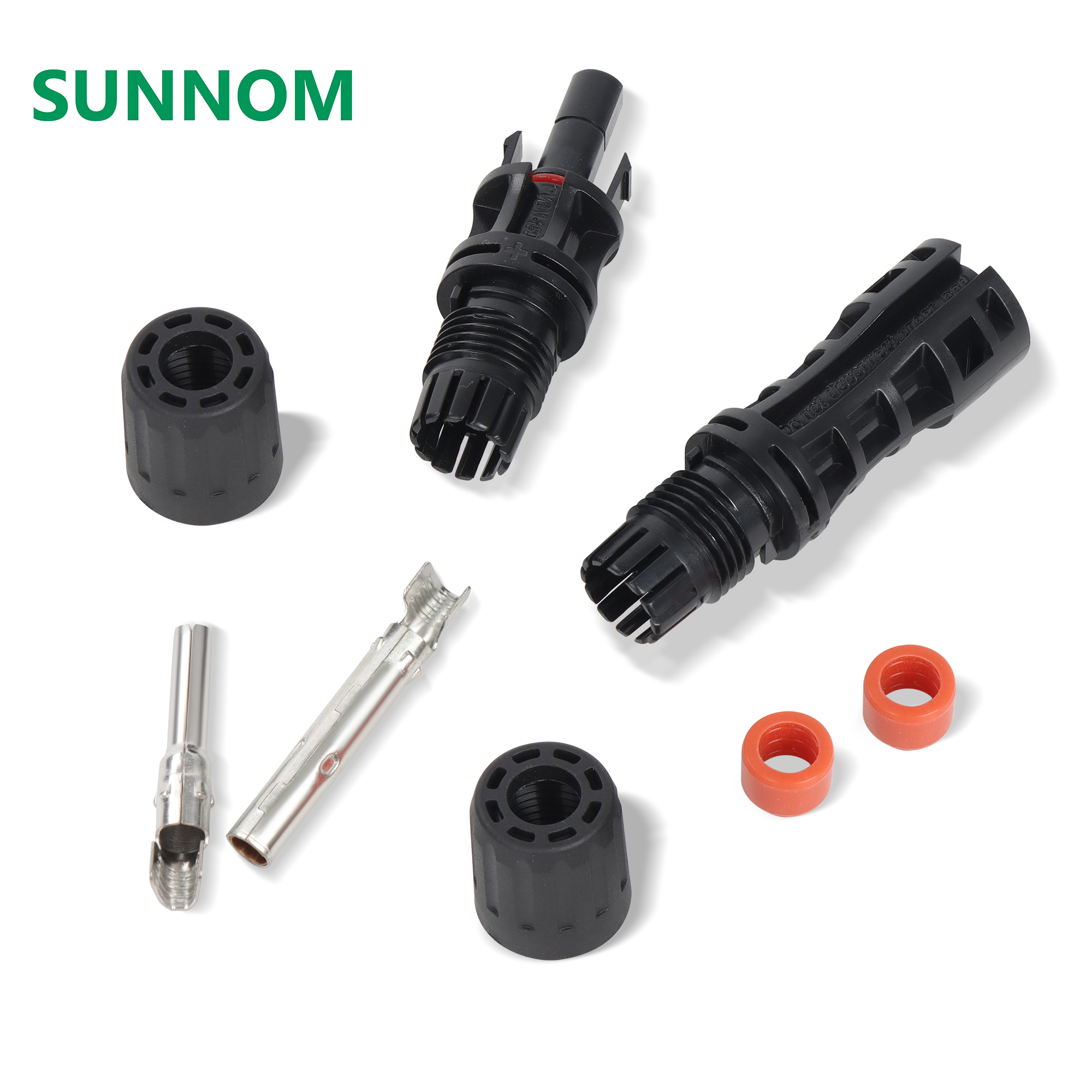
Q: How can solar engineers and EPC procurement teams manage the drift of contact resistance in 1500V solar connectors over a 25-year system lifecycle?
In utility-scale solar energy systems, components are expected to operate reliably in harsh outdoor environments for 25 years or more. While solar modules, inverters, and tracking systems receive significant engineering attention, the small PV connectors that link these assets together are often overlooked. However, as the industry transitions from 1000V to 1500V architectures, the electrical, mechanical, and thermal stresses on these connectors have intensified dramatically. One of the most critical, yet silent, failure modes in high-voltage PV arrays is the drift of contact resistance within the solar connector assembly. Over a 25-year lifecycle, this drift can lead to substantial power generation losses, localized heating, and catastrophic thermal runaway. This technical guide explores the mechanisms of contact resistance drift and details how engineers can mitigate this risk through material selection and design.
Understanding Contact Resistance and Its Drift over Time
Contact resistance is the electrical resistance found at the mating interface of two electrical conductors. In a solar connector, this interface is where the male and female copper alloy contact pins meet. Ideally, this resistance is incredibly low, typically measured in fractions of a milliohm (less than 0.25 to 0.5 milliohms). This low resistance ensures that electrical energy is transmitted from the PV panels to the inverter with minimal power dissipation.
However, contact resistance is not static. Over years of service, the resistance at this mating interface tends to drift upward. This phenomenon is known as contact resistance drift. In a 1500V system, where current levels can routinely reach 15A to 30A due to the use of high-power bifacial modules and larger string configurations, even a minor drift in resistance can lead to severe issues.
According to Joules law (P = I2R), the power dissipated as heat is directly proportional to the resistance and the square of the current. A connector that begins its life with 0.2 milliohms of resistance might dissipate negligible heat. However, if that resistance drifts to 5 milliohms or 10 milliohms over 15 years, the heat generation can spike, leading to temperatures that exceed the melting point of the surrounding polymer housing, ultimately causing thermal failure and fire hazards.
Physical and Chemical Drivers of Contact Resistance Drift
To manage contact resistance drift, engineers must first understand the fundamental physical and chemical mechanisms that drive it. Several factors contribute to this degradation over a 25-year system lifecycle:
- Oxidation and Corrosion: Copper, the primary conductor in contact pins, is highly susceptible to oxidation when exposed to oxygen and moisture. Copper oxide is a poor conductor with high electrical resistance. Over time, if the connector seal degrades, moisture and atmospheric pollutants enter the housing, oxidizing the contact surfaces and driving up resistance. Galvanic corrosion can also occur if dissimilar metals are mated together.
- Thermal Cycling and Stress Relaxation: Solar arrays experience massive temperature swings every single day, expanding during the hot daytime sun and contracting during the cold night. This thermal cycling causes microscopic movement between the contact pins. Furthermore, the metallic spring elements inside the female connector, designed to maintain mechanical pressure on the male pin, suffer from stress relaxation over time. Under constant high temperatures, the metal springs lose their elasticity and exert less force, reducing the effective contact area and increasing resistance.
- Ingress of Dust and Particulates: In dry, desert, or windy environments, microscopic dust and silica particles can penetrate poor-quality seals. These non-conductive particulates settle on the contact surfaces, creating physical barriers that disrupt the metal-to-metal contact, leading to rapid resistance spikes.
- Fretting Corrosion: Small vibrations caused by wind loads on the cable strings can induce microscopic rubbing at the contact interface. This fretting wear removes protective metal platings, exposing the raw base copper beneath to rapid environmental degradation.
The Compounding Threat of 1500V System Architectures
While contact resistance drift is problematic in any electrical system, it is exceptionally dangerous in 1500V DC installations. High-voltage arrays operate under high electrical field stresses, which lower the threshold for electrical breakdown.
When contact resistance drifts upward and generates heat, the surrounding air inside the connector housing can expand and dry out. If the resistance continues to rise and the mechanical joint loosens due to housing deformation, the electrical current may jump the gap, creating a localized electric arc. In a 1500V DC system, an arc can be self-sustaining, burning through the connector housing and cable insulation, creating a severe fire hazard on rooftops or ground-mounted arrays.
Additionally, high-voltage systems often utilize larger wire gauges and carry larger mechanical cable tensions. If these mechanical tensions pull on the connector housing, they can warp the internal contact alignment, exacerbating the spring relaxation and accelerating resistance drift.
How SUNNOM Connectors Mitigate Contact Resistance Drift
Wenzhou Shangnuo (SUNNOM) has engineered its PV connectors specifically to combat the long-term threat of contact resistance drift in 1500V installations. Our design philosophy focuses on material integrity, high mechanical force, and superior environmental sealing:
- High-Purity Oxygen-Free Copper Contacts: SUNNOM contact pins are fabricated from high-conductivity, oxygen-free copper. This base material provides the lowest possible bulk resistance.
- Heavy-Duty Tin Plating: To prevent copper oxidation, SUNNOM applies a thick, high-uniformity silver plating (typically 3 to 5 micrometers) to all contact surfaces. Silver not only has the highest electrical conductivity of any metal but its oxides are also electrically conductive, ensuring that even if slight oxidation occurs, the contact resistance remains low.
- High-Force Crown Spring Bands: Inside the female terminal, SUNNOM utilizes a specialized, high-resilience stainless steel crown spring band. Unlike standard copper-alloy spring contacts, stainless steel maintains its mechanical spring force and elasticity even under continuous exposure to temperatures up to 110 degrees Celsius, effectively eliminating stress relaxation over 25 years.
- Dual-Ring IP67 Silicone Seals: To block the ingress of moisture, corrosive gases, and dust, SUNNOM connectors feature a dual-ring sealing gasket made from premium-grade silicone. This robust seal maintains its elasticity and physical integrity across extreme temperature ranges, securing an IP67 protection rating over the long term.
- Premium PPO/PC Housings: The connector housing is made from pure, imported Polyphenylene Oxide (PPO)/Polycarbonate. This high-performance thermoplastic has an exceptionally low thermal expansion coefficient, preventing housing deformation and maintaining perfect axial alignment of the internal contacts.
Field Best Practices for Solar Engineers and EPCs
In addition to selecting high-quality connectors like SUNNOM, EPC contractors and solar engineers must implement strict quality control protocols during construction and operation:
- Eliminate Cross-Mating: Never mate connectors from different manufacturers, even if they physically fit together. Mismatched mechanical tolerances and plating materials always accelerate contact resistance drift.
- Precise Crimping Calibration: Ensure that field technicians use calibrated, high-precision crimping tools. A loose crimping joint creates a high-resistance point right at the cable-to-pin interface, which behaves exactly like internal contact drift.
- Regular Thermal Imaging Audits: During routine operations and maintenance (O&M), employ aerial or handheld infrared cameras to scan connector strings. Connectors with drifting resistance will stand out as thermal hot spots, allowing O&M teams to replace them before catastrophic failure occurs.
By combining SUNNOM high-performance connectors with meticulous installation and monitoring standards, solar project developers can ensure their 1500V assets deliver maximum energy yield and remain perfectly safe for their entire 25-year operational lifecycle.